

-
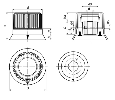
Code D H h m d d3 d4 d5 h1 h3 Dm d1 H10 Q CAD 47004638400 38 37 7 11,5 30 18 4,5 M5 16 5,5 12 6 26 
47004653400 53,5 45 9 11,5 43 23 5,5 M5 16 13,5 12 8 24 47004666400 67 53 11 12 54 31 5,5 M5 16 13,5 14 8 30 47004680400 80 60 13 12 65 36 5,5 M5 16 19 16 8 30 47004693400 93 67 13 12,5 78 50 6,5 M6 18 23,5 18 8 32 Material: PA Black reinforced polyamide resistant to oils and greases.
Galvanised steel insert with smooth through bore (tolerance H10).
Central cap in polyamide color RAL 7035.
Black pad-printed arrow on grey flange RAL 7035.
3 galvanised self-tapping screws 2.9x9.5 UNI6954.
Working temperature between +135°C and -20°C.
Options:
Version with black flange and cap, and grey arrow.
Flange graduated scale with numbers from 0 to 9 with 100 graduations.
Data Sheet (PDF) 

Lowered key in compliance with DIN 6885-2
d bxh t2 t1 d-t1 12 4x4 1,1 3 9 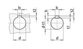
-
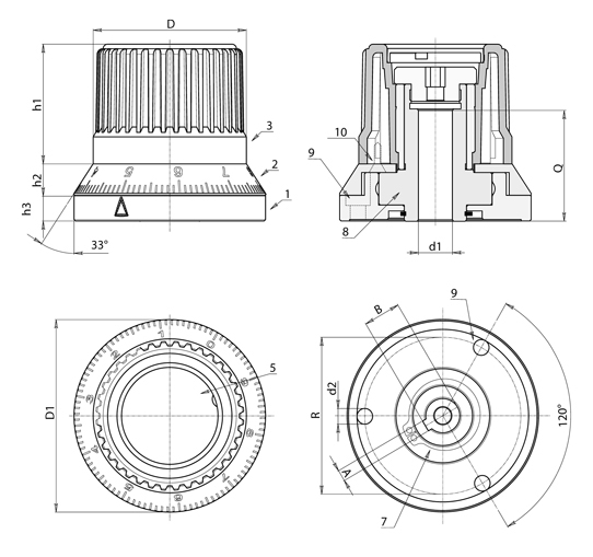
Code D D1 h1 h2 h3 R d2 A B d1 H7 Q CAD 47004654500 54 67,5 42 11 9 55 5,5 4 13,1 12 39 -
Materials:
1. Stainless steel (AISI 304) fixing base with friction device seat and fixing holes.
2. Anodized aluminium graduated flange (alloy 2011).
3. Reinforced polyamide control knob. Resistant to oils and greases.
5. PA6 cap.
6. Stainless steel fastening cap with hexagon socket (Aisi 303).
7. Fastening snap ring in stainless steel (UNI 3653).
8. Stainless steel (AISI 304) lock and friction mechanism.
10. Stainless steel self-tapping screws (AISI 303) TCS 2.9x13 for fastening the flange.
Graduated flange:
The standard numbering of the flange goes from 0 to 9 with 10 graduations for each unit. (100 graduations).
Fastening & coupling:
Fixed to the machine with 3 x M05 hex socket head cap screws (number 9 in the drawing) (DIN 912).
The shaft is coupled to the knob by means of a shaft with keyway. Attention! The key, for technical reasons, is small in size. See attached diagram for bore/shaft dimensions.
The shaft hole is machined to H7 tolerance. Side fixing hole is not required. The diameter of the hole is fixed and cannot be varied.
Features:
The main feature of this item is the possibility to continually adjust the axis of the machine to which it is coupled and to maintain the selected position. The special friction device, the heart of the mechanism, allows you to make very small, continuous movements and therefore enables fine tuning in both directions. After reaching the desired position, the friction device prevents rotation by any minor shaft-induced vibrations or movements. This system prevents accidental or involuntary rotations of the shaft.
Limitations:
If the vibrations are strong the friction device is not sufficient to block any movements. Moreover, the knob cannot support the weight of the shaft, consequently it does not replace the normal support systems (bearings, flanges, etc.). The knob cannot be installed if there is a motor drive present.
Data Sheet (PDF) 

Lowered key in compliance with DIN 6885-2
d bxh t2 t1 d-t1 12 4x4 1,1 3 9
-
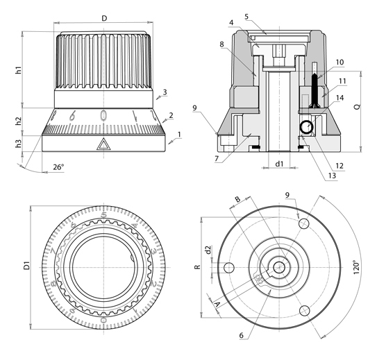
Code D D1 h1 h2 h3 R d2 A B d1 H7 Q CAD 47004654600 54 67,5 42 14,5 9 55 5,5 4 13,1 12 44 -
Materials:
1. Hardened steel C45 base with fixing holes.
2. Aluminium (alloy 2011) flange with laser engraved numbers.
3. Reinforced polyamide control knob. Resistant to oils and greases.
4. Stainless steel fastening cap with hexagon socket (Aisi 303).
5. PA6 cap.
6. Fastening snap ring in stainless steel (UNI 653).
7. High resistance tempered and hardened steel rotating cam shaft, with through hole and key.
8. Stainless steel knob insert (Aisi 303).
10. Stainless steel (Aisi 303) self-tapping screws TCS 2.9x19 for fastening the bush.
11. Aluminium (alloy 2011) turned unlocking pin holder bush.
12. Stainless steel (Aisi 302) pressure spring.
13. Hardened stainless steel locking roller (Aisi 52100 grade G2).
14. 2 turned stainless steel unlocking pins (Aisi 303).
Graduated flange:
The standard numbering of the flange goes from 0 to 9 with 10 graduations for each unit. (100 graduations).
ATTENTION!!: Select the rotation direction (O= clockwise A=counter clockwise).
Fastening & coupling:
Fixed to the machine with 3 x M05 hex socket head cap screws (number 9 in the drawing) (DIN 912).
The shaft is coupled to the knob by means of a shaft with keyway. Attention! The key, for technical reasons, is small in size. See attached diagram for bore/shaft dimensions.
The shaft hole is machined to H7 tolerance. Side fixing hole is not required. The diameter of the hole is fixed and cannot be varied.
Features:
The main feature of this product is the automatic locking function once the knob is released. This makes it possible to lock the shaft to which the knob is attached in the desired position. The start of the knob's rotation serves to unlock the internal mechanism, either by turning the knob clockwise or counterclockwise. Once the rotation of the knob stops, the spring rotates the knob in the opposite direction and the automatic lock is activated. The use of this system avoids accidents or involuntary rotation of the shaft.
Limitations:
The knob is not capable of supporting the weight of the shaft to which it is coupled; consequently it does not replace the normal support systems (bearings, flanges, etc.). The knob cannot be installed if there is a motor drive present.
Data Sheet (PDF)
PRODUCTS ![]() OPERATING ELEMENTS
OPERATING ELEMENTS ![]() CONTROL KNOBS
CONTROL KNOBS
470046KNURLED KNOB WITH INSERT WITH SMOOTH HOLE AND FLANGE
470046 PCKNURLED INDEXING KNOB WITH STEPLESS POSITIONING
470046 PCBKNURLED INDEXING KNOB WITH STEPLESS POSITIONING AND LOCKING ACTION